40 civil 3d cut and fill labels
AutoCAD Civil 3D Tutorials - Autodesk AutoCAD Civil 3D. The tutorial exercises are organized in a logical sequence, based on how you typically work with the different types of features. However, you may complete the exercises in any order you choose. After you begin an exercise, you should complete the steps in the order presented. Calculating Average End Area Cut & Fill Volumes using Civil 3D In the old days; average end area cut and fill volumes were calculated manually from paper cross sections representing a proposed roadway design. Today, using Civil 3D, we can extract average end area volumes with only a couple clicks of the mouse. The key to calculating corridor volumes is found in Civil 3D's sample lines.
Welcome to the AutoCAD Civil 3D Tutorials - Autodesk Each tutorial set contains exercises that are designed to explore the various features of AutoCAD Civil 3D. The tutorial exercises are organized in a logical sequence, based on how you typically work with the different types of features. However, you may complete the exercises in any order you choose.

Civil 3d cut and fill labels
Surface Modeling for Infrastructure Design - Creating an existing ... Add surface styles, labels, and tables to convey surface information on your design plans and work with volume surfaces for calculating cut and fill. Finally, wrap up the lesson by creating boundaries for surfaces. After completing this lesson, you'll be able to: Understand surfaces and how they are used in Civil 3D. Build surfaces from project ... Using Civil 3D to Create a Cut & Fill Earthwork Exhibit As an example, you could create a surface style that highlights positive and negative elevations to colorize the cut and fill areas throughout a project site. Once these areas have been defined, a custom spot elevation label style could be used to identify the amount of cut and fill going on in these areas. Civil 3D Tip: Adding Section Labels to Section Views - EnvisionCAD 1. Ribbon >> Home tab >> Create Design Panel >> Section Views >> Project Objects To Multiple Section Views 2. Select a section view group. 3. The Project Objects To Multiple Section Views dialog will appear. 4.
Civil 3d cut and fill labels. Civil 3D_Cut & Fill Exhibit Labels - YouTube This video will take the Cut & Fill Exhibit we previously created and show you how to add some extended data labels. We review creating the label so that it references 3 different surfaces and... Label Styles | Civil 3D 2017 | Autodesk Knowledge Network Create a Surface Spot Elevation label style named "Cut Fill." In the Label Style Composer dialog box, on the Layout tab, change the Name property of the label component to "fill." Change its color to Green. Edit the text component and change the Sign Modifier to Hide Negative Value. Creating Cut/Fill Volume Points or Labels in Civil 3D When you need to show cut and fill values at specific points within Autodesk AutoCAD Civil 3D, first you will need to create a volume surface. Place the desired points (or labels) which have a label style which shows the elevation, using the volume surface as the selection when prompted. PDF Cut Fill Spot Labels - amsworkplace.com 2. Create the spot elevation label style. • Toolspace Settings>Expand Surface>Expand Label Styles>Right click on Spot Elevation and click New. • Name the label style as desired. (i.e. Cut or Fill [0.08 inch]) • Specify the Text Style and Layer in the General tab. • In the Layout Tab change the default Component Name to Cut.
Creating Cut/Fill Labels for a Volume Surfaces in Civil 3D Creating Cut/Fill Labels for a Volume Surfaces in Civil 3D - YouTube Learn how to create one Label Style to easily display the cut or fill depth in a Volume Surface by using Label Expressions.-... Road design With AutoCAD Civil 3D + Open Chanel Design | Udemy This course was created to show you how I build successful Design a Complete Road and open channel, Roundabout in AutoCAD Civil 3D, in 2022 and beyond I'll take you from the very beginning and show you, over-my-shoulder, how I: Major Highlights of The Course lecture-1 Import Points and Basic Setting 1. Drawing Settings 2. Unit settings 3. Express yourself using expressions in Civil 3D - GovDesignHub 5) Create a label style that has 2 components, Cut and Fill text. These components reference the Surface Elevation, but in the text height property, you will set the corresponding expression (Cut/Fill). 6) Change the CUT component color to RED. 7) Change the FILL component to BLUE. 8) Test this out by using your new label style to label a surface!! Making CUT/FILL Maps in AutoCAD Civil 3D | Part II | ZenTek To begin, let's create the label style we'll need for Cut/Fill mapping. Go to Toolspace > Settings> Surface > Label Styles > Spot Elevation and right-click to create a new style (below). We'll call it CUT-FILL. Next, click on the "Layout" tab and delete the default text entities there.
Band and Code Set Styles (CAD Clinic: Civil 3D Tutorial) - Cadalyst A code set uses code, link, and shape styles to annotate corridor values in a section view. Band Sets. A band set defines what band types and styles appear when applying the set. For example, the band set below uses three band types: surface, horizontal geometry, and superelevation. Each band type has list of styles from which to choose. Expression Driven Cut and Fill Labels | Training Video - cadpilot Kyle demos a classic and basic Civil 3D Cut and Fill Label Style that is modified with Label Style Expressions. Yes. It is also possible to hide the chaff created in this example. This requires a Set of Expressions that work together instead of a pair and the thoughtful use of the Text Component Editor (TCE) component properties. Cut Fill (3D Analyst)—ArcGIS Pro | Documentation Illustration CutFill_3d (Before_Ras, After_Ras, OutRas) When the Cut Fill operation is performed, by default, a specialized renderer is applied to the layer that highlights the locations of cut and of fill. The determinant is in the attribute table of the output raster, which considers positive volume to be where material was cut (removed), and negative volume where material was filled (added). How to label volume surface with FGL NGL and cut fill depth labels in ... Spot elevation on grid for volume surface Spot elevation on gridVolume surface labelingJoin this channel to get access to perks: ...
About Label Styles | Civil 3D 2019 | Autodesk Knowledge Network
Label Styles | Civil 3D 2020 | Autodesk Knowledge Network Create a Surface Spot Elevation label style named "Cut Fill." In the Label Style Composer dialog box, on the Layout tab, change the Name property of the label component to "fill." Change its color to Green. Edit the text component and change the Sign Modifier to Hide Negative Value.
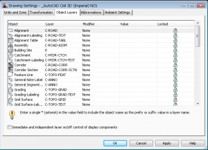
Civil 3D Template Development Part 3 - Drawing Settings - The CAD Masters
Volme grid map with cut fill labels - Civil 3D & LDD - AutoCAD Forums Civil 3D & LDD ; Volme grid map with cut fill labels Volme grid map with cut fill labels. labels; grid; fill; cut; volume; ... I am trying to create a volume grid map showing cut fill elevation differences at the grid corners and labels in each grid square stating how much cut fill is in that square. I created 2 tin surfaces, Existing Ground ...
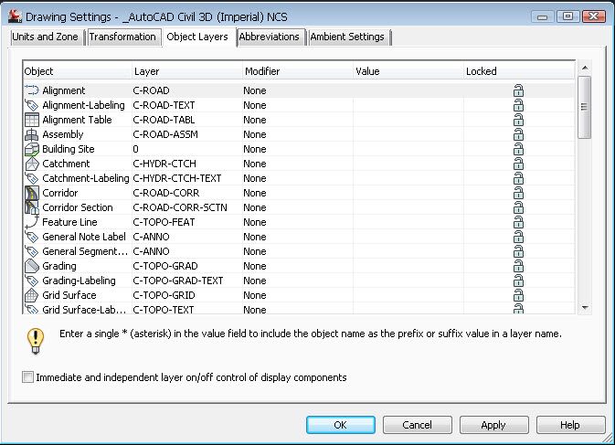
Civil 3D Template Development Part 3 - Drawing Settings - The CAD Masters
Cut/Fill Color Map - Carlson Software The Limit Cut/Fill Map Range option is a way to draw the color map only for a specified range such as only showing the deep cut. The Auto Set function fills out the cut/fill ranges based on the current two surfaces. The Set By Interval function fills out the cut/fill ranges by a user-specified depth interval.

Learning Civil 3D: Adjusting Individual Labels in Civil 3D
Plot Long Sections - Civil Survey Solutions First: Select the Civil 3D Profile, Profile Style to apply to the Existing Surface, then pick [OK]. Second: Select the Civil 3D Profile, Profile Style to apply to the Design surface, then pick [OK]. Third: Select the Civil 3D Profile View, Profile View Style to apply for the Long Section, then pick [OK]. Fourth: Select the Civil 3D Profile View, Band Style to apply to the Long Section, then ...

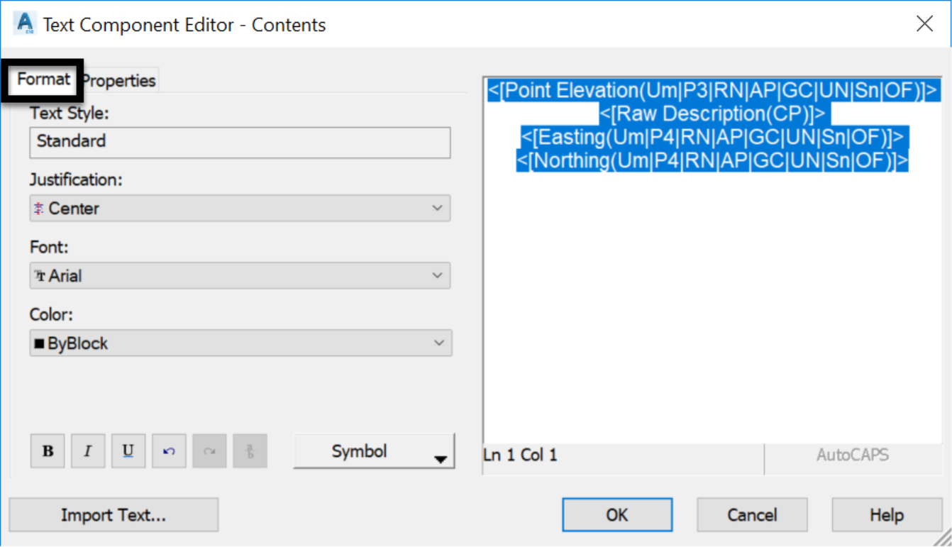
Express Yourself: Using Expressions in Civil 3D - AUGI Create a label style that has two components: Cut and Fill text (see Figure 7). These components reference the Surface Elevation, but in the text height property, you will set the corresponding expression (Cut/Fill). Change the CUT component color to RED. Change the FILL component to BLUE. Figure 7

Earthwork Plan Production | Autodesk AutoCAD Civil 3D 2020 - Earthwork Calculations
Dynamic Surface Cut-Fill Ticks! FINALLY. - civil4d.com [Note - make sure the color and plot styles are byblock - not bylayer] Modify the label to include two blocks, plus and minus using the size of the two equations above [might want to rename them from minus scale to minus size]. Turn Off the Marker and now you have cut fill ticks, all in color.
Creating Civil 3D Label Styles
Civil 3D Volume Surface (Cut and Fill) - Infratech Civil For Cut and Fill Factor, let's use 1.10. These factors control, depending on the soil type, how much the material swells after removal, or how much it is compacted when put in place. This means that for every cubic meter or feet of cut material we will need to haul 1.1 cubic meter or feet. Obviously, it would be the inverse for the fill material.

PDF AutoCAD Civil 3D Tutorials • Each tutorial set contains exercises that are designed to explore the various features of AutoCAD Civil 3D. The tutorial exercises are organized in a logical sequence, based on how you typically work with the different types of features. However, you may complete the exercises in any order you choose.

Civil 3D for Civil Engineering: TIN Volume Surface
Solved: cut/fill surface labels - Autodesk Community If you're using the method where the surface label equation is an "IF, THEN" statement then one of the label's text size should be readable (0.08) and the other set at 0.01 (or something really small). The size is based on the surface difference expression so if they are both large and overwriting, look at your equation.

Civil 3D Reminders: Corridor - Daylight Cut and Daylight Fill
Civil 3D Templates - ZenTek Consultants The AutoCAD Civil 3D templates that ship right out-of-the-box, just don't cut it in the real world. We need AutoCAD Civil 3D templates to be professional, concise, and easy to use, but developing the hundreds of display and label styles you need to get going is a time consuming and complex undertaking. That's where ZenTek can help!

Civil 3D Tip: Adding Section Labels to Section Views - EnvisionCAD 1. Ribbon >> Home tab >> Create Design Panel >> Section Views >> Project Objects To Multiple Section Views 2. Select a section view group. 3. The Project Objects To Multiple Section Views dialog will appear. 4.
Smart Retaining Walls - Civil 3D: Fierce Solutions
Using Civil 3D to Create a Cut & Fill Earthwork Exhibit As an example, you could create a surface style that highlights positive and negative elevations to colorize the cut and fill areas throughout a project site. Once these areas have been defined, a custom spot elevation label style could be used to identify the amount of cut and fill going on in these areas.
AutoCAD Civil 3D 2018 Tip: Use Civil 3D Line Label Styles to Annotate Utility Linetypes ...
Surface Modeling for Infrastructure Design - Creating an existing ... Add surface styles, labels, and tables to convey surface information on your design plans and work with volume surfaces for calculating cut and fill. Finally, wrap up the lesson by creating boundaries for surfaces. After completing this lesson, you'll be able to: Understand surfaces and how they are used in Civil 3D. Build surfaces from project ...

Solved: Civil 3D Labels on transparent labels plot incorrectly in 2019 - Autodesk Community


More on Civil 3D Labels (CAD Clinic: Civil 3D Tutorial) | Cadalyst
Post a Comment for "40 civil 3d cut and fill labels"